
Walser Pistenraupen Modellbau
The Pistenking AlpinFlex tiller is already a feast for the eyes out of the box, but with little effort additional details can be implemented to make it virtually indistinguishable from the original.
You will need a lathe, soldering iron, material such as brass and aluminum rods, silicone wire, springs, screws and some patience. The individual steps are described here for the PistenBully 400.
The printed parts are available at the AT modellbau Thangs/Shapeways webshop.
For the flap cylinders, printed parts are available at the AT modellbau webshop, with which these parts, including the hydraulic connectors, can be created quickly and absolutely true to the original. The hydraulic connectors suitable for the side finisher cylinders and the lifting cylinder of the Pistenking tiller are also included.
Additionally required are 2 mm silver steel round rods for the piston rods, M1.6 screws and silicone coated wire for the hydraulic hoses.
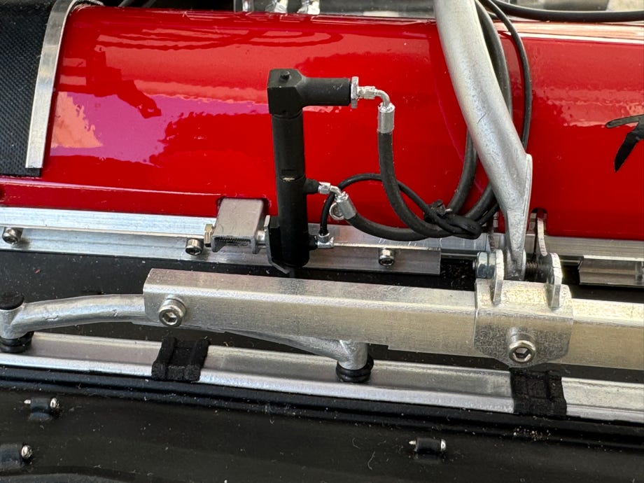
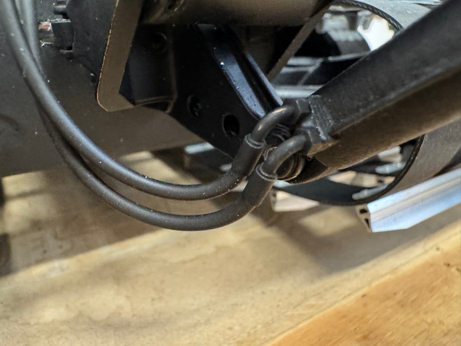
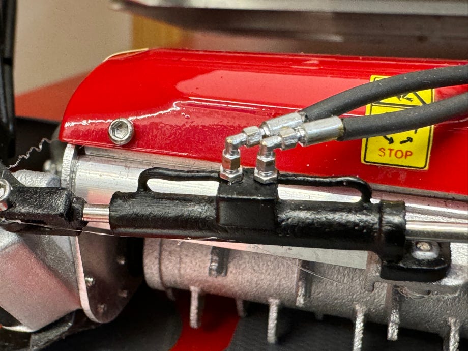
In the photos you can see the arrangement of the left and right flap cylinders and the hydraulic connectors:
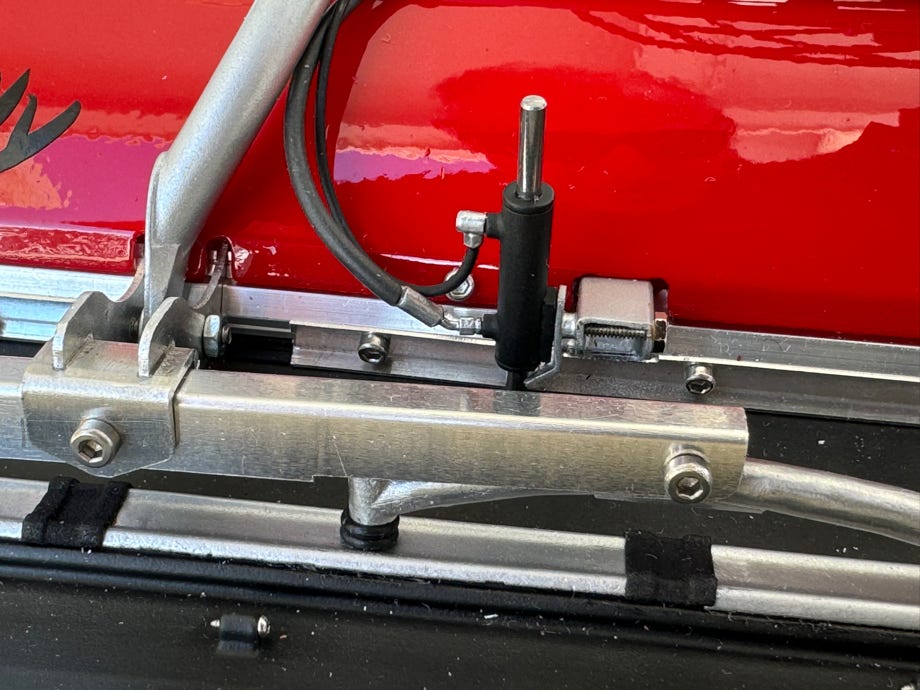
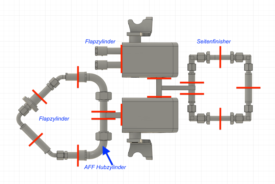
Below, the separation points on the printed part are marked with red lines, as well as which hydraulic cylinders the connecting parts are to be used for. Short (approx. 2.5 mm) brass tubes with an outer diameter of 2.0 mm are soldered or glued to the cylindrical ends. The stripped part of the wire is glued into this. See photos above for reference.
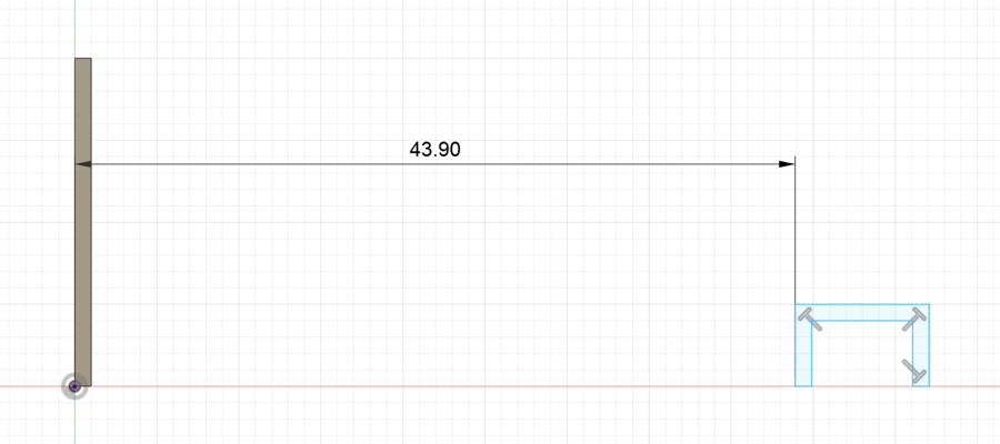
The brackets are installed at a distance of 43.9 mm from the inside of the tiller box, see drawing. A corresponding recess must be cut into the red covers (see photo above). The brackets are attached to the tiller box with a short M1.6 screw. An M1.6 thread is cut into the flap cylinder for attachment and this is attached to the bracket with an M1.6x10mm screw. The piston rods are glued into the holes, and a piece of piston rod is also placed at the top of the left cylinder.
The hydraulic hoses are routed directly to the hydraulic distributor cover on the right and glued there; the hoses for the left cylinder also end there. They can be guided through the openings in the brackets for the snow overthrow shields at the back of the tiller frame.
The pictures below show the connections on the lifting cylinder and the side finisher cylinders:
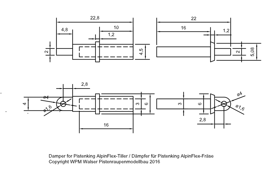
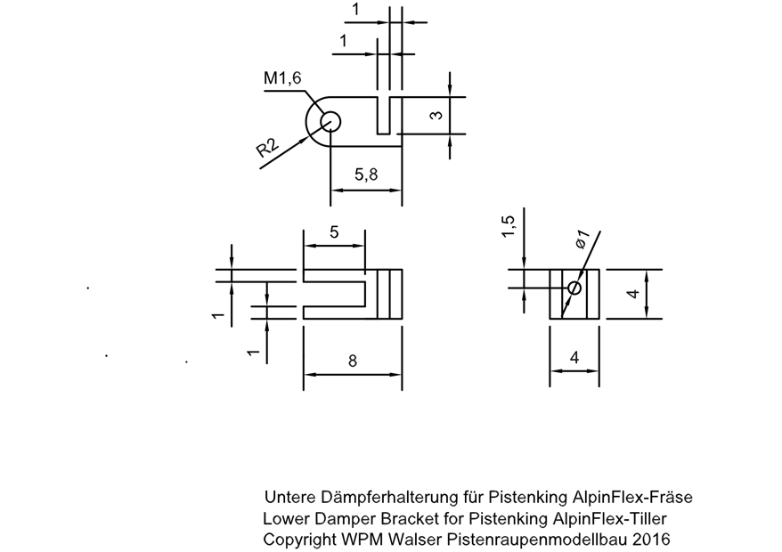
The drawings mentioned in the Rad & Kette article can be downloaded as a PDF below (just click on the image):
Diese Seite verwendet Cookies. Sie stimmen der Verwendung von Cookies durch Anklicken von “OK” zu. Nähere Informationen finden Sie in unseren Datenschutzbestimmungen.
This page is using Cookies. You are permitting the use of cookies by clicking on “OK”. More information can be found at our Privacy Protection.


